Optical Power Meter (OPM)
The VeEX Inc Optical Power meters are made with fast and accurate testing in mind. They are used to measure the power running through a cable at a given wavelength, and interface with phone, PC, or other VeEX devices to save and generate reports on the findings. This information is used to verify that the cable span is working correctly and to find the source of the problem when it's not. When paired with a VeEX Optical Light Source (OLS) or as part of a VeEX Optical Loss Test Set (OLTS), which includes both, WaveID can be used to quickly test several wavelengths without having to adjust the OPM settings.
|
|
Only optical power meters (e.g. Built-in or FX4x/8x OPM series meters) approved by VeEX are supported. WaveID will work with OLS in CW mode only. Accessing the Optical Power Meter module shuts down GPS and the atomic service. |
|
|
Do not connect the fiber before opening the OPM application. First, zero the meter with the dust cap closed before making any measurements. |
Connecting to the internal (built-in) OPM
- Tap the X icon to close OTDR mode. The Fiber main menu appears.
- Tap Optical Power Meter on the main menu. The OPM screen appears with the Caution warning.
Alternatively, access the OPM screen by selecting Optical Power(USB) from the Platform menu.
Connecting an External OLTS Device
- Insert USB dongle into the test set's microUSB port and connect it to a VeEX Inc. supported Optical Light Test Set (OLTS) device before launching the application.
- Power on the external meter.
- Select the connected external meter and tap Connect to proceed to the external OPM menu or Use Internal to use the built-in OPM menu if it supported by the test set. The OPM screen appears with the Caution warning.
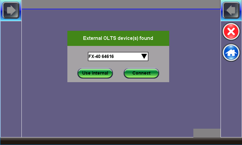
The Name of the External OLTS device is Displayed Once Detected
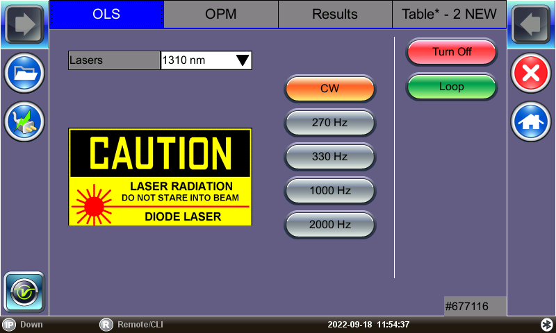
OLS Menu
Setup and Measurements
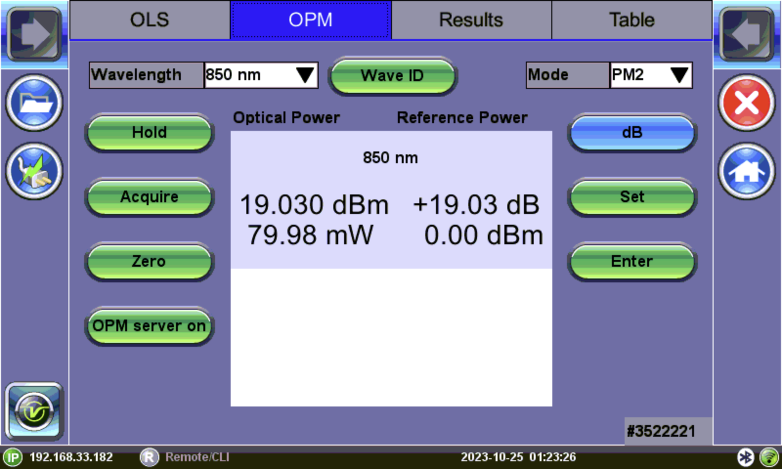
OPM Menu
![]()
- Wavelength: Matches the calibrated wavelength to the signal being measured.
- Wave ID: Detects the incoming wavelength automatically from a supported VeEX Inc.OLS. Use when operating the OLS in continuous wave (CW) mode with or without Loop enabled.
- dB/dBm: Switches between dB and dBm measurement units. A Green dB button shows absolute power level in dBm. A Blue dB button measures relative power loss in dB. Use the Set (Reference) and Enter (edit Reference) to set Reference, edit Reference, and view measurements in three units: dBm, dB, and Watts.
After toggling to the dB button to blue, the Set and Enter buttons appear. - Set: Sets the reference value for the current wavelength.
- Enter: Edits current wavelength reference value.
- Hold: Freeze measurement to the last power or loss reading on the screen. “HOLD” appears next to “Optical Power” when tapped. Tap Hold again to unfreeze it.
- Acquire: Loads current measured value into the Table tab. The Table tab indicates how many new records have been temporarily saved into memory. In manual IL test mode, the Acquire button must be used to capture each individual reading (e.g. same fiber at different wavelengths) unless Loop is turned on.
If your device is equipped with a built-in clock, the saved measurement result will have a time stamp.
- Zero: Recalibrates the OPM to treat current conditions as zero. Used when measurement conditions change significantly or to re-calibrate the OPM. Make sure the cover is shut on the OPM test port before tapping Zero. When in doubt, recalibrate prior to making any measurements, e.g, when testing in cold outdoor temperatures and then moving testing into a heated building.

Put the cover over the OPM test port BEFORE recalibrating.
- OPM Server On:Remote control feature not currently supported. Broadcasts the IP address on the current network for users to connect to the test set module's built-in optical power meter through Ethernet/TCP/IP using Fiberizer LTSync Windows Desktop software for remote control and access.
-
Mode: Designates the measurement specification built-in: PM1 (-70 to +10dBm), PM2 (-50 to +25dBm), or PM3 (-65 to +15dBm). For specific information on the PM1, PM2, and PM3 specifications, see the platform's datasheet at www.veexinc.com.
Calibrating to Laser Source
To perform loss (dB) testing, the meter must be referenced (calibrated) to the Laser Source output.
To measure reference cable loss using the built-in light source (Loopback Referencing):
- If beginning testing, zero the meter by closing the dust cap and pressing the Zero button.
- Connect the port with the desired wavelength OLS to the OPM port using a patch cord.
- Turn on dB measurement by toggling the dB button to blue.
- Select the OLS tab, select the laser wavelength, and turn ON. Press Loop to cycle through all supported wavelengths.
- Select the OPM tab and select the measurement wavelength or press Wave ID to automatically detect the correct wavelength.
- Tap Set to record the 0.00 dB point. A reference point is established and the calibrated LS can be connected to the far-end of the fiber to measure the loss. Tapping Set will overwrite previously saved reference value(s).
To measure reference cable loss using an external light source:
- Connect the OLS to the OPM port using a patch cord.
- Turn on dB measurement by toggling the dB button to blue.
- Select the measurement wavelength. If using a supported VeEX light source in CW mode, pressing "Wave ID" automatically selects the correct wavelength.
- Tap Set to record the 0.00 dB point. A reference point is established and the calibrated LS can be connected to the far-end of the fiber to measure the loss. Tapping Set will overwrite previously saved reference value(s).
Measuring Power (dBm)
-
If beginning testing, zero the meter by closing the dust cap and pressing the Zero button.
-
Insert the fiber being tested into the OPM port.
-
Select the measurement wavelength. If using a supported VeEX light source in CW mode, pressing "Wave ID" automatically selects the correct wavelength.
-
Tap Acquire to record a result. Acquired results can be viewed from the Table tab and saved from the Results tab.
Measuring Loss (dB)
- Set reference values for all testing wavelengths (refer to [Calibrating to Laser Source] for more details.
-
Remove the reference cable and connect fiber to the OPM port on the unit.
- Tap Acquire to record a result. Acquired results can be viewed from the Table tab and saved from the Results tab.
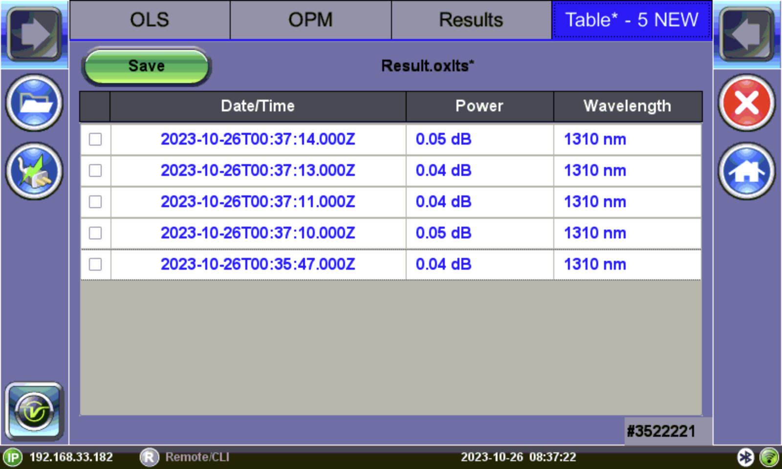
Readings (Table tab)
OPM readings appear in the Table tab. Saving readings will permanently write data to the Results tab. More than one reading can be saved at a time. Use this function to organize/filter results in project batches, so that the correct set of results are grouped together appropriately. Pressing Remove will permanently remove the readings from the current list.
To view and save (enter) test results into the Results table:
- Select the OPM tab. Verify the insertion loss (IL) values are acceptable, then tap Acquire to load values into the Table tab. The Table tab title shows how many fiber records have been temporarily saved in the format Table*-n NEW, where n is the number of new records.
- To view the active results table, select the Table tab.
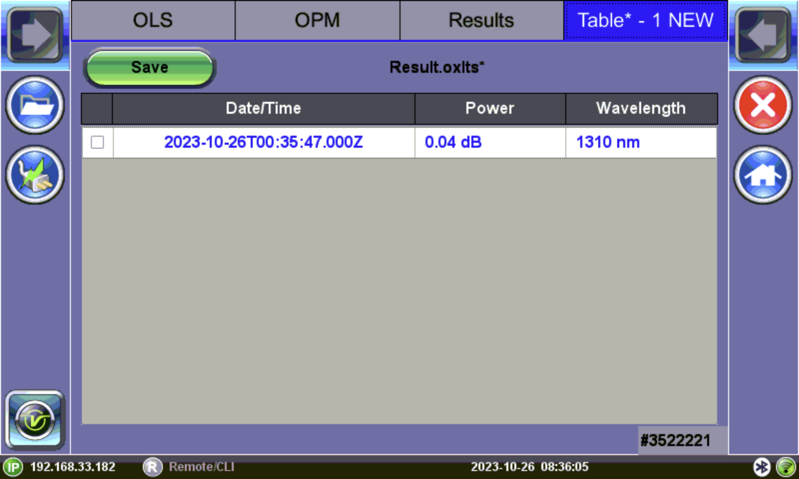
- To permanently save the fiber record locally, select the record(s) and press Save. The Result saving screen appears. The filename will default to the date/time stamp unless a specific file name is entered.
![]() The JobID/CableID/FiberID/TraceID fields determine the location to which the trace is saved. If these settings are not set accurately, the trace will not save to the desired location.
The JobID/CableID/FiberID/TraceID fields determine the location to which the trace is saved. If these settings are not set accurately, the trace will not save to the desired location.
-
Tap OK. The readings are saved to a file and the table resets.
To remove results before saving, select the checkbox next to the reading(s), then tap Remove.
After saving power or loss readings to a file, access the file in the Results tab.
Results
Results can be saved to the test set, exported to USB, or uploaded to Fiberizer Cloud.
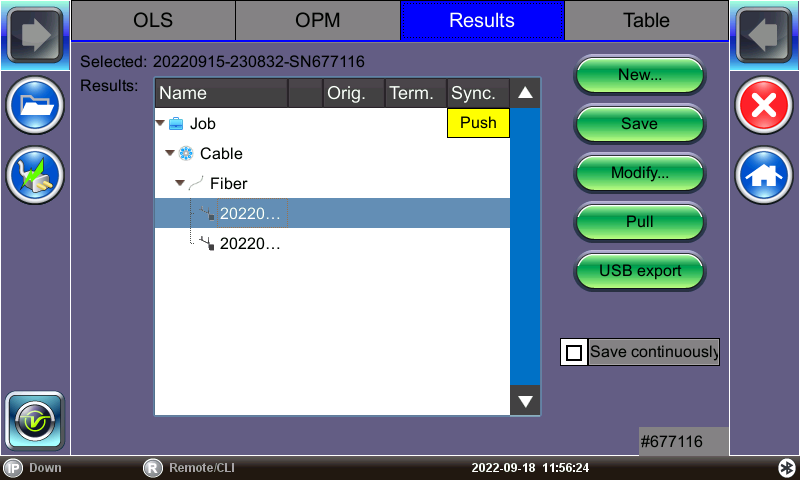
Results Management Menu
The results screen is used to view previously saved results. Test results can be pushed/pulled from Fiberizer Cloud. The directory displays the location of stored files. Connect to Fiberizer Cloud, then select the file(s) by tapping them. Refer to Fiberizer Cloud for details on connecting to Fiberizer Cloud. Refer to Results/Reports for more details on fiber test results.
Use the following options when using the Results screen:
- Push/In Sync: Uploads locally saved results to Fiberizer Cloud. In Sync indicates the results have been saved to Fiberizer Cloud successfully.
To push the results to Fiberizer Cloud, ensure connection to the network via Ethernet or WiFi,
and then tap Modify>Settings to sync with Fiberizer Cloud.
Then, tap Push to sync saved files to the cloud.
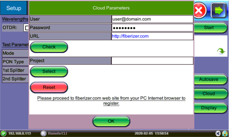
Fiberizer Cloud set up screen
- New: To create a new folder.
- Save: Saves results. Once saved, the files can be accessed in File Manager and R-Server (if available). Refer to Working with Saved Results, Profiles, Images and R-Server for more information.
- Modify: Select a file or folder in the directory to modify. Options to Rename, Remove, and upload the selection to Fiberizer Cloud are available.
- Pull: When connected, pulls file from Fiberizer Cloud onto the test set.
- USB Export: Exports files to a USB stick. Choose Export Group to retain the tree format (sub-directory) or Export Flat to create a single filename using sub-directories to build a name.
- Save continuously: To autosave results at a specified interval (1 to 60 seconds). Use this option to check power drift.